|
|
|
Who's Online
There currently are 6043 guests online. |
|
Categories
|
|
Information
|
|
Featured Product
|
|
|
 |
|
|
There are currently no product reviews.
 ;
Great manual very clear copied. You are making an incredible job. I appreciate a lot the rapidity and your efficiency. Thanks a lot
;
Good pdf of the service manual for this unit. Includes disassembly instructions, full schematics, board layouts, parts lists and diagnostic information. Some information is in the pdf twice (single pages, and split pages), but that could be how it was originally generated by panasonic, or perhaps the idea is to make it eaiser to put onto 8.5 x 11" pages.
Information was exactly what I needed. Delivery was overnight (less than 12 hours) and I was happy with the process.
;
5 STARS for FAST DELIVERY, BEST PRICES and QUALITY PRODUCT. Item was exactly as described with superb resolution. Will definitely source all my future requirements from this website. Thanks a lot owner-manual.com!
;
OEM manual provided all schematics, board layouts and component specs necessary to facilitate unit maintenance. All pages were clear and readable.
;
Good condition and quality. Hard to find anywhere in Internet, only on this site.
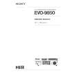
With Iron Wire: 1. Using desoldering braid, remove the solder from all pins of the flat pack-IC. When you use solder flux which is applied to all pins of the flat pack-IC, you can remove it easily. (Fig. S-1-3) 2. Affix the wire to a workbench or solid mounting point, as shown in Fig. S-1-5. 3. While heating the pins using a fine tip soldering iron or hot air blower, pull up the wire as the solder melts so as to lift the IC leads from the CBA contact pads as shown in Fig. S-1-5. 4. Bottom of the flat pack-IC is fixed with glue to the CBA; when removing entire flat pack-IC, first apply soldering iron to center of the flat pack-IC and heat up. Then remove (glue will be melted). (Fig. S-1-6) 5. Release the flat pack-IC from the CBA using tweezers. (Fig. S-1-6) Note: When using a soldering iron, care must be taken to ensure that the flat pack-IC is not being held by glue. When the flat pack-IC is removed from the CBA, handle it gently because it may be damaged if force is applied.
2. Installation
1. Using desoldering braid, remove the solder from the foil of each pin of the flat pack-IC on the CBA so you can install a replacement flat pack-IC more easily. 2. The ��� mark on the flat pack-IC indicates pin 1. (See Fig. S-1-7.) Be sure this mark matches the 1 on the PCB when positioning for installation. Then presolder the four corners of the flat pack-IC. (See Fig. S-1-8.) 3. Solder all pins of the flat pack-IC. Be sure that none of the pins have solder bridges.
Example :
Hot Air Blower
Pin 1 of the Flat Pack-IC is indicated by a " " mark.
Fig. S-1-7
or Iron Wire
Presolder
Soldering Iron To Solid Mounting Point Fig. S-1-5 Flat Pack-IC CBA CBA Fine Tip Soldering Iron Fig. S-1-8
Flat Pack-IC Tweezers Fig. S-1-6
1-4-3
TVDVDN_SN
|
|
|
> |
|